


- Block diagram
- Design considerations
- Design resources
- Product listing
- Support
Block diagram
Highlighted components are Nexperia focus products.
AC EV wallbox
Related systems (1)
Power Factor Correction (PFC)
DC/DC conversion
Battery Management System
Related systems (1)
Transient Voltage Suppressors (TVS)
Recommended products (1)
Reverse battery protection
Power regulation and management
Recommended products (3)
MOSFET gate driver
Recommended products (2)
Gate biasing
Signal conditioning
Recommended products (3)
ESD protection
Recommended products (2)
Select a component
To view more information about the Nexperia components used in this application, please select a component above or click on a component (highlighted in blue) in the block diagram.
Design considerations
- Designers have multiple options for OBC conversion topologies, including single-phase / multi-phase and uni- / bidirectional
- Current batteries are typically 400 V, using 650 V FETs in a bidirectional OBC topology where GaN brings the highest efficiencies (for unidirectional topologies SiC diodes can be used on the secondary side
- For 800 V batteries, need to go multi-level GaN or high-voltage SiC
- However, OBC topologies are heavily fragmented which may lead to combined 650 / 1200 V device solutions
- PFC output defines blocking voltage of power semiconductors at DC-DC-Input and battery voltage defines blocking voltage at DC-DC-Output (650 or 1200 V)
- Trend towards higher OBC charging power and 800 V batteries for higher class BEV solutions, will require more 1200 V solutions

Check out Nexperia's new application techbook on Integrated OBC and DCDC converters
For a comprehensive understanding on the latest development and solutions for Integrated OBC and DCDC Converters systems, download our new techbook and :
- Understand the new design approaches
- Discover Nexperia's product offerings for various high voltage topologies and low voltage control board interfaces
- Explore various design challenges and how Nexperia's products are curated to overcome them
- Discover all recommended products for the OBC and DCDC Converters
Design resources
Evaluation boards

NEVB-NPS3005 - 0.5-5.5 V, 6 A, 15 mΩ single channel load switch with soft start evaluation board

NEVB-NEX90530BPA-Q100 - 3-40 V, 300 mA ultra-low Iq LDO evaluation board

NEVB-NXF6505A-Q100 - 5.5 V, 1.2 A, 160 kHz push-pull transformer driver evaluation board

NEVB-NCA9548A_NCA9547 - 8-channel I²C switch and multiplexer evaluation board
NEVB-NXU0204 - Unidirectional 4-bit (2+2) voltage translation evaluation boards
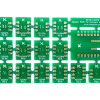
NEVB-LOGIC02 - DIL footprint (XSON / X2SON / TSSOP / VSSOP) adapter board